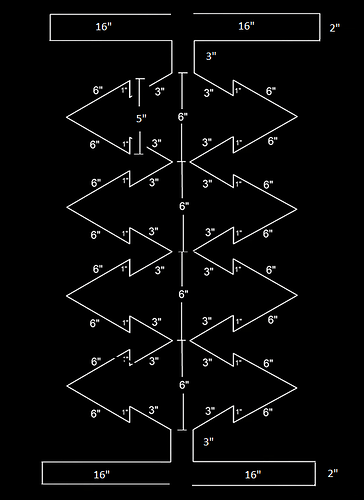
6abc (WPVI) is a low VHF signal. This antenna is a UHF and high VHF antenna. The VHF elements are for channel 7 and upwards. Since it is one continuous wire over 120" that may satisfy low VHF requirements but no guarantee.
The channel 6 frequency (82 mgz) has a wavelength of 12 feet (144"). You may have to try this second version and make the folded top and bottom VHF elements 16" each instead of 10". Altogether these with the UHF bends will add up to 144":
Also these VHF elements will have to be 3" rather than 2" from the fractal ones. If that doesn’t work, I can suggest another DIY antenna (customized for solely VHF channel 6) which can then be combined with a UHF antenna.
One possible problem with the Tuxedo antenna - excessively long VHF elements may interfere with the 4 UHF bays. If the 16" lengths interfere with the UHF signals, cut them to 15 or 14 and see if that still retains both UHF and low VHF. This will be a trial and error experiment because of the low VHF aspect… Will be interesting to see how this antenna handles low VHF.
PS a reflector (cardboard & aluminum foil) will help: 40" x 40" five inches back of the antenna.
Thanks for the information, please send along information on an antenna to be used for 6abc only so I have that in my back pocket as well. Maybe I will build both. And 6abc is a non starter with my Tablo setup. I had it for the longest time and then it simply stopped coming in. Same thing happened to a buddy a few streets over.
Right now I am having an issue where nothing on NBC10 will seem to record from hd homerun to plex. It keeps missing recordings on that channel and I keep getting recording failed tuner issue messages. But my Tablo nails the recordings all the time. I want to see if the uhf antenna will improve things from the hd homerun perspective and since it is going in the attic, no one will see it. I have no problem combining two antennas or even having them on separate tuner boxes.
Running OS x in the house presents challenges on getting apps to move recordings from Tablo to plex. Not many custom home grown apps out there for mac osx. And it still does not solve my 6abc reception issue.
Here’s what I would do for low VHF (channel 6) - a loop antenna. This is an idea I have putting together several sources.
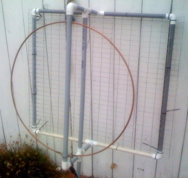
- First here is my current hi VHF antenna (a 21" diameter\60" circumference loop of copper refrigerator tubing 1/2" thick) to get channels 8 and 11:
The PVC pipes are there just for support - the actual antenna is the copper wire loop (chicken wire in the back as reflector).
- I’m also an HD Radio fan and needed a strong enough FM antenna (in the low VHF band) to fit in the attic. I saw this design, copied it and it works great:
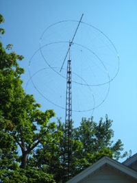
These are three 36" diameter\114" circumference 6 gauge copper loops standing up spaced 21" apart on my attic floor.
If one looks at these two antenna designs, a lo VHF attic antenna could probably be made as a loop (or set of loops to strengthen it). Begin with one loop of 6 or 8 gauge wire 144" in circumference (46" diameter) standing up on the attic floor. Does not have to be copper wire. Leave a 2" gap at the bottom and attach the balun ends on each side of the gap.
If that does not bring in the channel, add a second loop behind it (same size) to act as reflector (or build a square reflector from cardboard and aluminum foil). Put the reflector about 21 inches behind the receiving loop.
If this doesn’t bring in channel 6, add another loop 21" in front of the receiving loop. This will concentrate and focus the incoming signal onto the receptor loop. This is what I call building the antenna “system” in stages (as needed) instead of creating one huge (monolithic) structure immediately.
This is how I built my FM-HD radio antenna in the attic - stage by stage in a modular fashion. It occupies at most a 40" spread along the floor (46" tall). NONE OF THE LOOPS HAVE TO BE CONNECTED IN ANY WAY - just standing next to each other in a row. Easy to build. Reflectors and receptors don’t have to be connected by booms. My HD Radio antenna brings in all the station IBOC signals at 80 to 100%. My hi VHF antenna brings in channel 10 at 85% and channel 8 at 100% so loops are effective in dealing with VHF and FM signals.
I prefer loops to a long, wide singular Yagi antenna that takes up most of the attic space (and is tough to maneuver). Plus it makes moving the antenna around the attic in parts very easy. Oh BTW how did I get my FM loop antenna to stand up on the attic floor? I brought up an old wooden coat rack to the attic and propped it against that!
If you build a separate VHF antenna then you would need a UHF-VHF joiner to combine the two. Or get a preamp such as the RCA TVPRAMP1Z which has separate UHF and VHF inputs (which is what I did).
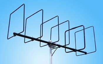
This approach is not unique. Cubical quad antennas are used all the time to get FM (VHF band) signals:
1 Like
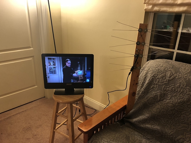
So playing around tonight I took an fm antenna I had laying around. One that came with my receiver. I stripped the ends of each and tried to create a simple dipole.
I was able to pick up abc but it was pixelated pretty bad. I only had it placed in my master bedroom, could not work in the attic while wife is asleep.
I even tried adding the rca preamp you mentioned and it did not improve things. I wanted to see if this would pick up anything. I am using this site to create the dipole, http://users.wfu.edu/matthews/misc/dipole.html
I am going to stop at Home Depot or Lowe’s tomorrow and pick up some twin lead 300 ohm wire and try again.
Again, I am testing things out. If that does not work, I’ll try the rings you sent me photos of. I know height will make a difference and I I will try this in the attic before doing anything else.
I simply do not understand why I cannot get this channel. I am able to get 2.1 and the sub channels with the rig mentioned above, but again, they are pixelated.
And my measurements when I did the math said the dipole will be approx 10 feet long. I find that hard to believe, I believe I did the math right based on the web page.
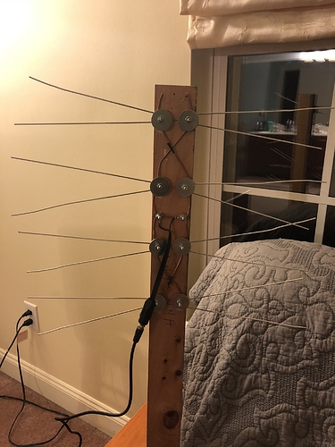
Like I said, I’m just playing around trying to pick up this station. I did create a 4 bay bow tie out of coat hangars and it picked up all of my uhf channels and was flawless. No pixelation at all.
The channel 6 frequency (82 mgz) has a wavelength of about 12 feet (144"). A half wavelength is 6 feet. So that calculation (10’) is about right for a full wavelength dipole. The circles would be about 144 inches (diameter 46"). A less powerful antenna (half wavelength dipole) would be 6’ or 72".
There was a channel we should have easily been getting in my area and it was pixelating badly. We phoned the station and they sent an engineer to look at the antenna and sure enough there was a problem they had been unaware of for several MONTHS! Since hardly anyone was using that station OTA, they weren’t paying attention to their own antenna! After they fixed it, the channel came in crystal clear. Their antenna was on a mountain so they had to send an engineer up there…
If you do the circles, use 6 gauge wire (thicker wire makes a difference) or 8 gauge. Doesn’t have to be copper, can be aluminum or steel. One of my circles is a bent steel rod I had lying around in my basement. A similar antenna I created for my cousin used bicycle rims as circles he had in his garage from an old bicycle!
The nice thing about the circle antenna is that one can easily add incrementally another circle in front of the others to strengthen the reception.
Talking about adding stages to an antenna, take a look at what this person did for his VHF antenna needs:
He extended his original VHF antenna twice using the same antenna parts to bolster its power.
1 Like
So, finding someplace that sells 300 ohm wire is proving to be a challenge, no dice at ACE HW or Home Depot. or Lowes. Times like these I really miss Radio Shack! Could I substitute a different wire type for the dipole? I am guess probably not.
I may need to go the copper tubing route after all. This is so frustrating. Funny thing, the guy at home depot when I was there is a town or two over and he says he gets 6abc with his antenna. I’d like to see it to believe tbh, but hey, all good.
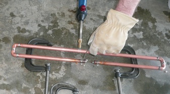
Any wire will do for an antenna. 300 ohm wire was used in the past because the connections to the old analog TVs and radios was 300 ohm. But in itself it is nothing special or magical. Some folded dipoles for VHF & FM (see picture below) use copper pipes (I used refrigeration copper coil tubing for my antennas):
The thicker the diameter of a wire, the better. Electromagnetic signals and current scoot around the outside of a wire on its skin. The larger the diameter space…
These days baluns replace the past 300 ohm connection as they are 300\75 ohm transformers for coax device connection.
A circle antenna (or cubical quad loop) in fact is a set of folded dipoles in series.
“Funny thing, the guy at home depot when I was there is a town or two over and he says he gets 6abc with his antenna.”
It could be the location within your attic. I had to search inside my attic for the optimum antenna placement. There are some spots in my attic that are “null spots” - they don’t receive ANY signals.
How far are you from the 6abc transmission tower? If closer than 7 miles, you can be under it of all things. You may have to fool around with the antenna spot and angles. At least the summer is ending and the attic will be cooler.
I’m about 15-20 miles at most from the towers. There are some trees at the bottom of my street, but house is at the top of the court, so I would think the trees would be a non-issue. Maybe the new comcast building is messing things up.
I like the idea of using the tubing the way you did and soldering it all together like that, might be more stable in my attic that way. The other thing I was thinking was to make my own set of rabbit ears out of copper wire cut to length. If they were to work, I could attach them to the new 4 bay antenna I made for my uhf signals.
That 4 bay antenna seems to be performing as good as if not better than my clearstream 2V. Although I think that is better for hi-vhf signals.
I can see abc on the Tablo, its either one red martian, 3 orange, or all green. But it is never clear. It is pixelated and causes dropped or missed recordings.
I have some things to consider for sure, how are you connecting the balun to the copper tubing and mounting the dipole in your image?
Here is my FM band antenna for HD Radio (which signals are hard to get and therefore I needed to make a special antenna). I created in my attic what this person had on his roof (previous post and picture of the circular cubical quad loop):
http://www.ezoantennas.com/
Picture 1 shows the entire antenna (reflector, receiving loop, directing loop):
Picture 2 shows the receiving loop hung on a coat rack (a true coat hanger antenna LOL):
Picture 3 shows the reflector - a set of 70" rods:
Since these pictures were taken I have added an additional director loop at the front (not shown).
The loop shown behind the reflector is another director loop to catch a station coming from the backside. It projects that signal through the reflector spaces onto the receiving loop.
The rod going through the center of all these loops is to catch a station coming from the side of the antenna.
All this gives me HD Radio at 90 to 100% signal strength (I have a Sangean HD Radio).
Since FM sits on the VHF band midway between lo and hi VHF, I’m assuming that this same strategy would work for lo VHF television.
How is the balun connected? Picture 2 at the bottom shows the balun connected to the receiving loop. I took a standard balun bought at Lowes and cut off the end connectors so I would have just the balun wires. The receiving loop is a circle with a 2" gap. Stripped the balun wires, wrapped one balun wire around the left loop wire (one inch from the end) and the other balun wire around the right loop wire. Just wrapped them hard around the refrigerator coil tubing that is the antenna.
There are 21 inches from the reflector to the receiver. Another 21" from receiver to director. In all 42" in length and 48" tall. I can move it around one part at a time because the parts are not connected and are free standing. Even a Yagi antenna can be built this way because the boom that connects all the parts (reflectors and directors) is irrelevant to signal reception.
BTW the copper pipe dipole is not my antenna - just an example of another approach using pipes. Refrigerator coil tubing runs like $10 for 120" at Home Depot (1/4" diameter).
My guess is that rabbit ears could work in the attic for lo VHF. Rabbit ears made from two coat hangers (each hanger when straightened out will give you about 40"). I once made a hi VHF one bay bowtie from coat hangers - each one was about 33" and it got the hi VHF channels at 100%.
This is the bow tie I recently made for uhf.
All from coat hangars.
What I am struggling with are the dimensions I need to create the dipole. I am having trouble wrapping my head around the dimensions.
Channel 6’s wavelength is 12 feet. A full wave antenna (dipole) for channel 6 is 144". That should be the length of the dipole.
A less powerful dipole would be the half length antenna which is half the above - 6 feet or 72".
The full wave folded dipole would be this:
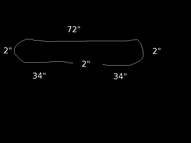
One piece of wire, tube or pipe 144" long. Folded in half - 72" on top, 2" on each side, 34" on the bottom (left and right) with a 2" gap.
The balun wires would attach to each side (the bottom 34" segments).
Attach this dipole to a separate wooden pole. Stand it about 3’ away from the UHF bowtie. Join the two antennas via a UHF-VHF joiner (coax from each antenna’s balun) or through the RCA amp mentioned before…
Why two separate poles? A lo VHF antenna can smother a UHF antenna and distort its signals.
BTW a lo VHF antenna normally functions best 8’ above ground level. So putting it in a first floor room may cancel its effectiveness.
You could try a half wave dipole (one half those dimensions above) and see whether a 72" antenna (instead of 144") brings in the signal. Folded in half, the half wave comes out to 36" long (3’) instead of 6’.
An alternate approach would be to extend the 4 bay bowtie. At the top add another bay of 40" elements (bent in two the V shape sides would be 20"). The top feedline wires would have to be extended upward a few more inches to accomodate the new bay. That would be equivalent to adding rabbit ears to the bowtie.
I thought about adding the rabbit ears to the bow tie, but I Think I would prefer to keep things separate first.
I am giving this a shot over the weekend. Having your photo is what I was thinking.
When attaching the balun, should I strip the wires and wrap them like you did the rings. Or should I solder these to the tubing?
I did both. I first wrapped the stripped balun wires around the tubing. Then for good measure I applied some solder to them on the tubing to have a solid connection. I didn’t want to have a good antenna build only to be compromised by a flimsy balun connection that leaked the signal.
Exactly, should I use a heavier copper wire to connect the balun and wrap it around the tubes? Or can I just get some bare copper wire from Home Depot, connect them and solder away?
You read my mind! I actually wrapped 14 gauge copper wires to the antenna ends several twists (about 3 to 4 inches). Each copper wire was about a foot long. Really wound those two wires around the tubing tightly. Then intertwined the balun wires with the other ends of those copper wires (about 3 inches) and also applied solder to the intertwined balun wire\copper wire from antenna.
Adding VHF rods directly onto UHF antennas has a negative effect. People have discovered that doing so has VHF distorting the middle UHF frequencies. So I kept my VHF antenna separate from my UHF antenna.
Let me correct something about baluns here. At first I tried those from Lowes and wasn’t thrilled with their performance. I ordered the outdoor Channel Master baluns from Home Depot (more sturdy) and eventually settled on those even if they were used indoors. I had to order them online from HD because the instore guy at HD didn’t know what the heck a balun was!!! He kept saying, “Won’t your cable company give you one?”
Ha sounds like the guy I was talking to today at the depot.
I have some pvc piping, I was gonna mount the uhf bow tie to the pvc mast I’ll call it and I was hoping to mount the dipole on a “t” above it.
Any ideas or recommendations on how to mount the dipole above the bow tie and 3 feet behind?
I guess I can use the amp I have and combine the two?
 Will be interesting to see how this antenna handles low VHF.